

Rigid Couplings for Precision Motion Control Applications


, which are sometimes called sleeve or muff couplings, have been historically imprecise, inexpensive, and often home made components for simple shaft to shaft connections. In the past many people would not consider using a rigid coupling in any servo application. However, smaller sized rigid couplings, especially made of aluminium, are increasingly being used in motion control applications due to their high torque capacity, stiffness, and zero backlash.
Rigid couplings are torsionally stiff couplings with virtually zero windup under torque loads. If any misalignment is present in the system the forces will cause the shafts, bearings or coupling to fail prematurely. Rigid couplings cannot be run at extremely high rpm’s for the reason that they cannot compensate for any thermal changes in the shafts which is caused by the high speed use. However, in situations where misalignment can be tightly controlled rigid couplings offer excellent performance characteristics in servo applications.
A sometimes overlooked advantage of rigid couplings is they can be used to establish shaft alignment in misaligned systems. To establish shaft alignment the motor and component mounts need to be loosened to ensure there is free movement. Then connect the shafts with the rigid coupling which, if precisely made, will align the shafts. Lastly, center the components on any remaining free play and tighten the mounts.
Required features for Motion Control
There are several features required of rigid couplings to ensure proper performance in motion control applications. The most important feature is that the coupling itself does not introduce misalignment into a system where it cannot be absorbed without damage to bearings and seals. The strictest control of shaft alignment will result when the bores are honed, since honing assures that both bores are collinear. Honing also corrects any residual distortions caused by stresses introduced during the manufacturing process, resulting in a round, precisely sized bore. Proper sizing and geometry assures a large percentage of shaft contact and greater torque transmission ability.
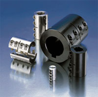
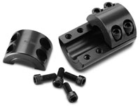
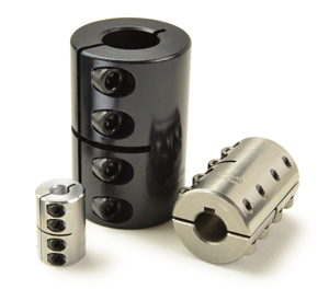
The simplest form of rigid couplings has set screws to fasten the coupling to the shaft through screw impingement. The problem with is any adjustment of the set screw causes damage to the shaft. A superior alternative would be the clamp-style rigid coupling since it wraps around the shaft to provide high torsional holding power without the shaft damage. have the additional benefits of allowing for disassembly and maintenance without removal of other components. When the hardware on a two-piece rigid coupling is opposing, the coupling can be operated at higher rpm since it is dynamically balanced. As a guideline, can be evaluated for applications up to 3000 rpm. The guideline can be increased to 4000 rpm when a two-piece style with opposing hardware is used.
Rigid couplings lack a mechanism to absorb the vibration inherent in many mechanical systems. Vibrations can cause hardware to loosen and torque transmission ability to diminish during normal use. Placing a nylon treatment on the screw threads can reduce the effect of vibration on the hardware for increased coupling reliability. The nylon also provides the necessary material to reduce galling of the screw threads in stainless steel couplings.
Proper Installation and Special Design
Most clamp-style rigid couplings have been designed with cap screws close to one another and arranged in pairs. Especially when combined with a cross-cut, this design facilitates greater holding power and also accommodates slight deviations in the size of the two shafts being connected. It is recommended that this style of coupling be by tightening the paired screws alternately in several steps. This is because the close proximity of the screws results in a mutuality of the hoop stress developed in the coupling by each screw in a pair. As each screw is tightened it tends to relax any tension developed by its companion. Alternately tightening the screws in several steps distributes the tension more evenly, assuring a tighter fit and the desired holding power.
A less common but sometimes useful type of rigid coupling is the three-piece clamp-style. This design allows for more convenient exchange or adjusting of coupled shafts, particularly where the shaft cannot be axially detached. Either side of the coupling can be detached and the shaft removed without disturbing the other shaft connection. The three-piece rigid coupling design also accommodates a slightly larger variation between the sizes of the shafts being connected by clamping independently on the two shafts.
Summary
Selecting a coupling for a servo application involves many different performance factors. These factors include torque, shaft misalignment, stiffness, rpm, space requirements, and others, that all must be satisfied for the coupling to work properly. The benefits of rigid couplings include their economy, high torque capacity, torsional stiffness, and zero backlash. Precisely manufactured rigid couplings with honed bores are increasingly used in motion control applications where components are properly aligned. Frequently, the coupling itself is used to establish the needed alignment. In addition to motion control
applications, rigid couplings are often used to connect line shafting or other components such as a motor
to a gearbox.
Performance Parameters of Rigid Couplings
| Torsional Rigidity |
Torsional Strength |
Maintenance Required |
Electrically Isolating |
Bearing Loads |
Inertia |
| High | High | No | No | High | Varies |
| Constant Velocity |
Zero Backlash |
Cost | Angular Misalign. |
Parallel Misalign. |
Axial Motion |
| Yes | Yes | Low | Zero | Zero | Zero |