

Servo Coupling Selection for Vision and Optical Inspection Systems
Machine vision and optical inspection systems are high tech, multi-purpose applications that require high precision components. A machine vision system can be used for a number of tasks where it essentially replaces the human eye with a camera. The applications vary and no two systems are exactly alike, but there are two common traits between all machine vision systems - the need for motion and a demand for precision.
Designers of machine vision systems must select components that meet the high demands for their application. One important component is the zero backlash coupling, and there are more than a few from which to choose. The user must determine the best coupling for the system based on the specifics of the application. There is a degree of give and take when selecting a coupling, as each one has its individual strengths and weaknesses.
Machine vision systems usually operate with one of two general modes of movement. One type is the stop-and-go motion system that moves quickly to one spot, takes a picture, and then moves swiftly to another location and takes another picture. Inherent in this type of system is vibration caused by rapid starts and stops and components, such as couplings, that dampen vibration will help reduce settling time and increase through-put.
A second type of system operates in constant scanning mode. Unlike stop-and-go systems, which only require accuracy upon stopping, these systems must maintain accuracy while scanning. This necessitates the use of a coupling with high torsional rigidity. Vibration may be less of an issue in systems that scan.
In addition to vibration dampening and torsional rigidity, important coupling selection criteria for machine vision systems are misalignment, inertia, speed, and torque capabilities. Speed and torque are fairly straight forward concepts, but misalignment and inertia can be more complex. There are three types of misalignment that must be considered - parallel, angular, and axial motion - and often more than one type exists in an application. A coupling that cannot accommodate the type and amount of misalignment present in a system will likely fail. Depending on the coupling used, misalignment can also result in high bearing loads that can lead to premature failure of the bearings.
Inertia is the coupling’s property to stay at constant speed unless acted upon by a force. In other words, inertia is the amount of force that is required by the system to start the coupling from a rest, or to stop it during motion. In even more simplified terms, inertia refers to the coupling’s mass. In the case of a stop-and-go system it would seem best to utilize a coupling that has low inertia, to conserve the system’s energy and provide less wear on its components. Inertia is less of an issue for systems that operate at motion all of the time.
This article will review six different types of couplings. The strengths and weaknesses of each coupling will be highlighted as they relate to the machine vision application. All couplings reviewed have zero backlash since this is essential to the accuracy of machine vision and inspection systems. Zero backlash ensures that there is no play between components of the coupling. In other words, if one shaft turns 90 degrees, a zero backlash coupling guarantees that the other shaft will turn the same 90 degrees.
• Max Speed: 6,000 RPM
• Excellent misalignment capabilities
• Low to moderate torsional rigidity and torque capacity
• Vibration dampening
• Low inertia
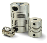
Beam Couplings
Beam couplings utilize continuous cuts in the body to transmit torque and accommodate misalignment. They are a good fit for machine vision systems that operate at a moderate speed - maximum of 6,000 rpm - have significant misalignment, and do not require torsional rigidity for scanning applications.
Two common variations of the beam coupling are single beam types with one long continuous cut, and multiple beam types that have one or two sets of shorter cuts overlapping each other. Generally, a coupling with a fewer number of longer, continuous cuts will offer more flexibility than beam couplings that use a larger number of shorter cuts. Increased flexibility results in low bearing loads under angular and axial motion. On the other hand, if multiple beams are utilized, the coupling can better accommodate parallel off-set.
Beam couplings undergo a certain amount of windup when under torque, so they are less torsionally rigid than some other available couplings. This property may be desirable, however, for stop-and-go applications requiring dampening and decreased settling time. One can improve torsional rigidity in a beam coupling either by selecting a multiple beam type or one made of stainless steel instead of the more common aluminum. In the case of stainless steel, the heavy material off-sets aluminum’s advantage of having low inertia and there is a large increase in cost. Therefore, it is advisable to look elsewhere for a more torsionally stiff coupling.
• Max Speed: 8,000 RPM
• No misalignment capabilities
• High torsional rigidity
• High torque capacity
• VLow Inertia in aluminum body.
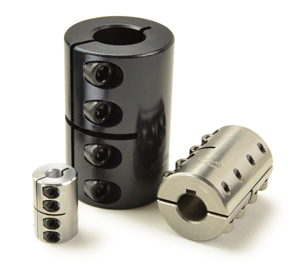
Rigid Couplings
Rigid couplings are exactly how they sound: rigid. They can be manufactured out of several materials and are available in a number of styles. Clamp style couplings, as opposed to set screw style couplings, are probably more applicable to machine vision systems. They provide better holding power by exerting clamping force onto the shaft while set screw style couplings only rely on the screws themselves. Clamp style rigid couplings do not require maintenance, provide better holding power, and do not cause damage to the shafts.
The rigid coupling has the highest rated torsional rigidity, making them ideal for scanning applications. They can withstand relatively high rpm and aluminum versions have low inertia. However, there is no misalignment capability in a rigid coupling and they do not dampen vibration, which means they could be problematic in stop and go systems. The bearing loads are the highest of all couplings and one must take extra care to make sure that the shafts of the system are perfectly aligned. Thermal expansion under extremely high speeds is also something to monitor, as rigid couplings have no means to accommodate the resulting stresses with the same effect as misalignment on the bearings.
As long as the shafts of the system are properly aligned and there are no thermal expansion issues, rigid couplings are a good option for the scanning type applications. They offer excellent torque ratings, are the most torsionally stiff coupling available, and require no maintenance.
•Small misalignment capabilities
•Low to moderate torsional rigidity and torque capacity
•Good vibration dampening
•Moderate inertia, but negated by vibration dampening characteristics
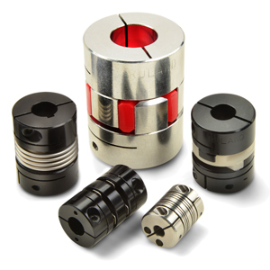
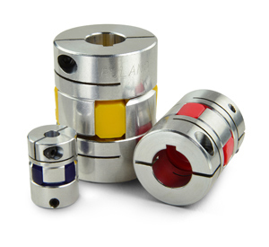
Zero Backlash Jaw Couplings
The zero backlash curved jaw coupling is a variation on the straight jaw coupling. The straight jaw design has inherent backlash and is not suitable for machine vision systems.
Composed of three parts - two aluminum hubs and an elastic insert referred to as the ‘spider’ - the curved jaw coupling press fits together for zero backlash operation. The design of the jaws of the hubs helps to reduce deformations that the spider may undergo during normal operation.
While curved jaw couplings can operate at high rpm, the strength of these couplings lies in the spider. The elastic material absorbs vibration, making it the best choice for stop and go systems that require a dampening component. Further, the spider is made available in several levels of hardness. The stiffer the insert is, the more torsionally stiff the coupling will be at an expense of some dampening capability.
Jaw couplings are not torsionally rigid enough to be placed on a scanning style system, even with the hardest elastic spider. Users with systems requiring a high degree of misalignment capability should look elsewhere as high bearing loads are the result of misalignment with a jaw coupling. Another consideration is that jaw couplings are fail safe, meaning the jaws of the hubs will lock together and continue to transmit torque if the spider fails. This may or may not be desirable, depending on the system.
The curved jaw coupling has superior dampening characteristics and the ability to mix and match the spiders with the hubs is an advantage as well. The inertia of the jaw coupling is relatively high when compared to other motion control couplings - on par with an aluminum rigid coupling - but this issue is negated with the dampening characteristics of the spider. The balanced design of the coupling enables it to be run at high rpm without causing vibrations. However, if there is a high amount of misalignment and importance is placed on rigidity during motion, it may be better to choose a different coupling type.
• Good misalignment capabilities; excellent parallel misalignment
• Good torsional rigidity with acetal center disc
• Little vibration dampening
• Low to moderate inertia
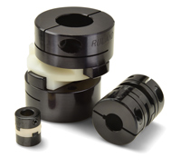
Oldham Couplings
Similar to the jaw coupling, the oldham coupling is also made up of three components, two aluminum hubs and an insert, which press fit together.
The oldham coupling has a few clear advantages. First is the ability to accommodate a high level of parallel misalignment, since the center disc is made to slide over the tenons of the hubs. This lack of resistance - other couplings have a spring-like resistance to misalignment - results in low, and stable bearing loads. The second advantage is the ability to interchange the center disc. Generally, two types of material are used, acetal to provide torsional stiffness and nylon to provide dampening, much like the jaw coupling. Furthermore, the oldham coupling has the unique ability to act as a mechanical fuse. The tenons of the hubs will not interlock if the center disc fails and torque will cease to be transmitted. The oldham coupling’s aluminum hubs help to keep the inertia low.
While the oldham coupling works very well for parallel misalignment, it can only handle small amounts of angular misalignment and axial motion. Too much angular misalignment will cause the coupling to lose its constant velocity characteristic and the coupling will literally fall apart with too much axial movement. Also, while nylon material may be chosen to dampen vibrations, due to the sliding of the hubs and extremely soft characteristics of the nylon used, the coupling is not tight enough to be zero backlash. Speed capability for all oldham couplings is also relatively limited, around 4500 rpm. Additionally, the sliding of the tenons will eventually wear down the insert and replacement will be required.
The ability to choose the center disc’s material for either torsional rigidity or dampening makes the oldham coupling a versatile option for machine vision systems. Since the settling time versus torsional rigidity conflict is quelled by this option, the remaining factors are speed and misalignment. For applications running less than 4500 rpm, with high parallel misalignment and little angular and axial motion requirements, the oldham is suitable for either stop-and-go systems or rigidity-minded scanning operations.
• Good misalignment capability
• Excellent torsional rigidity and torque capacity
• Low inertia
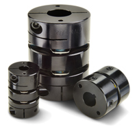
Disc Couplings
Disc couplings are either composed of two hubs joined by a flexible metallic center disc, or two hubs and a center piece joined by two metal discs. The double disc couplings can accommodate parallel and angular misalignment because the two discs are able to bend in different directions. Single disc couplings can only accommodate angular misalignment.
Both variations of the disc coupling are torsionally rigid. The discs are flexible and allow for an ample amount of misalignment, especially in the double disc design. Bearing loads and inertia are low as well. Furthermore, the disc coupling can handle upwards of 10,000 rpm, with low inertia due to the light materials used.
Due to the torsional rigidity, the disc coupling is best suited for applications where accuracy and strength are emphasized; it is not a good choice when dampening is needed. Disc couplings are therefore more suitable for scanning as opposed to stop-and-go vision systems. While the best coupling for accuracy and torsional rigidity is the rigid coupling, the disc coupling allows misalignment in the shafts while retaining high torque capabilities. The one drawback to the disc coupling is that they are delicate and can damage easily if installed incorrectly. If applied correctly, however, the disc coupling has outstanding qualities for torsionally rigid applications with misalignment.
• Good misalignment capabilities
• Excellent torsional rigidity and torque capacity
• No vibration dampening
• Very low inertia
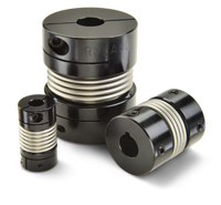
Bellows Couplings
The bellows coupling is constructed of two aluminum hubs connected, either by welding or an adhesive, to a metallic bellows. The two most common materials for the bellows are nickel and stainless steel. The bellows normally have a thin wall, which adds to responsiveness and accuracy. The flexibility of the bellows accommodates all misalignment types and bearing loads are low and constant throughout all points of rotation. With aluminum hubs, the bellows coupling has very low inertia ratings, which save the system from unnecessary force and provide even greater response.
All of these strengths do not compromise the coupling’s torsional rigidity, which is even greater than the disc coupling. Running speed capability is on par with the disc couplings at about 10,000 rpm. The bellows coupling is a great option for machine vision systems requiring accuracy, though vibration dampening is nonexistent. They can operate at high speed, have excellent torsionally rigidity, while still retaining good misalignment capabilities.
Conclusion
A machine vision system can only operate as well as the components that make it up. In this case the sum of the parts is greater than the whole. Each of the couplings discussed have their own strengths and weaknesses that make them ideal for a variety of different systems and applications. However, no one coupling can be applied to all situations. Based on this rationale, the zero backlash coupling should be considered in the early stages of system development. If the coupling’s performance characteristics meet the operating goals of the system, the user can be assured of maximum system performance and longevity.