

Selecting the Proper Beam Coupling for an Application
Choosing the most appropriate beam coupling to use in motion control applications can be confusing. This article examines the design differences and how to select the proper beam coupling.
In the design of motion control equipment, typically the coupling is left as one of the last components to be specified. In fact, couplings are often overlooked or taken for granted rather than treated as a critical part of the performance of the system. Selection of the proper coupling ensures the equipment will meet the requirements for performance and have a long, trouble free life. Conversely, poor coupling selection can leave designers and end users of equipment frustrated with imprecise positioning and frequent maintenance requirements.
Many types of couplings are available for motion control applications, each with their own pros and cons. One of the most popular and versatile types of couplings is the beam coupling. Beam couplings are an excellent starting point for designers because they do many things well: they have good misalignment capabilities, torsional stiffness for accuracy, and strength for carrying torque loads that allow them to be used in many applications. However, there are several different design categories for beam couplings that allow users to optimize characteristics to meet their needs, including material differences and beam pattern designs.
Criteria to consider for selecting a coupling
Before discussing the different varieties of beam couplings available in the market, there are some basic criteria that designers should gather and understand about their application before specification of a coupling can take place:
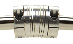
- Physical Space Requirements – Basic information such as shaft sizes, spacing between shafts, shaft geometry (round, D-bore, keyed, hex, polygon, etc) and overall envelope size are the first considerations for specifying a coupling. Special consideration should be paid to designs that have large differences in shaft sizing between driving and driven components, large spacing between shafts and small windows to fit a coupling. Also, applications that involve inch & metric shafts and/or non-standard shaft sizing/tolerancing can present issues in selection of a coupling.
- Misalignment – Shaft misalignment is one of the most critical pieces of information needed to correctly specify a coupling. Often times, designers and engineers don’t give this proper consideration and fail to calculate tolerance stacks and manufacturing inconsistencies adequately. Consequently they can misapply couplings in applications where shaft misalignment is greater than the coupling can accommodate resulting in poor performance and frequent maintenance. Angular ¶llel misalignment and axial motion (whether from push/pull motions, thermal changes, or simply play from bearings) must all be considered together.
- Environmental Considerations – Most motion control applications exist in controlled climates without extremes in temperature, moisture, chemicals or other environmental factors that can affect the coupling performance. However, some applications encounter conditions that are less than ideal. Extreme temperatures, both hot and cold, can decrease performance of beam couplings – material strength and elasticity/brittleness can be negatively affected. Other exposure possibilities include the presence of chemicals that could compromise the integrity of the material, operation within a vacuum with out-gassing concerns, or electrical current passing through the coupling whether intentional or incidental.
- Operating Conditions - Many factors exist here that designers need to be aware of when selecting a coupling. Conditions such as speed(RPM), acceleration/deceleration rates, rotational cycling - i.e. continuous, start-stop, reversing, duty cycle - intermittent, continuous – 24/7, 8hrs/day, etc. Torque must also be understood when specifying the coupling – not simply rated torque, but real torque seen by the system. Inertia loads especially in systems with rapid accel/decel curves and systems that encounter hard mechanical stops can have unexpectedly high real torques seen by the coupling. These factors must be considered when it comes to sizing a coupling correctly.
- Performance Criteria – Finally, performance expectations from the system must be considered. Level of positioning accuracy and repeatability, amount of settling time that is tolerable when the system reaches position and overall responsiveness of the system should all be taken into account for coupling selection. Additionally, consideration for factors such as dampening in the system against shock loading, need for electrical isolation, and overall expected life of the system and associated maintenance schedules should all be looked at by designers.
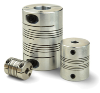
Two basic designs of beam couplings exist: single and multiple beam designs, both of which are machined from a single piece of material. Single beam designs consist of one long continuous beam that generally is several complete rotations in length. The long beam yields excellent angular and axial flexibility, however it is not nearly as effective with parallel misalignment. To effectively handle parallel offset, the single beam is forced to simultaneously bend in two different directions. This results in a large stress within the beam that can rapidly cause fatigue and subsequent failure of the coupling. The long single beam also suffers in torsional stiffness capabilities. Its benefit of flexibility under misalignment derived forces is a weakness in the degree of positional accuracy it can deliver. Under torque loads, especially during high rates of acceleration or deceleration such as starts and stops, the coupling “winds-up” like a spring causing an angular displacement from one end of the coupling to the other negatively affecting the accuracy of the driven end of the system. This windup results in a positioning lag between the driving and driven side of the assembly while in motion. Applications that require precise positioning throughout the entire path of motion may not be suitable for single beam couplings. Torsional stiffness is also a factor when motion comes to a stop. The angular lag of the coupling can force the servomotor to “seek” its position, causing an oscillation back and forth until the coupling can reach its original free length and the system comes to rest. Long settling times can negatively affect the speed and accuracy of the system.
Multiple beam couplings take a slightly different design approach to improve performance when compared to single beam couplings. They use a single or double set of overlapping beams as opposed to a continuous single beam resulting in beams that are shorter in length increasing torsional stiffness and positioning accuracy. The shorter the length of the beam, the stiffer and stronger it is under torsional loads. However, shorter beams are also stiffer under misalignment loading which reduces the overall ability of the coupling to compensate for manufacturing tolerances in application. The idea of nesting multiple short beams together into a single set of beams improves the ability of the coupling to accommodate misalignment. It still is not as flexible as continuous single beam coupling, but has enough flexibility to be able to be used effectively in almost all applications. The set of beams also creates greater strength due to having the beams work in parallel with each other to achieve higher torque capabilities. This configuration still suffers from issues with parallel misalignment and is even more susceptible to rapid fatigue do to the shorter length and stiffer beams.
Four and Six beam couplings
A further enhancement to the multiple beam design is incorporating multiple sets of multiple beams into a single coupling. Multiple sets of cuts adds an extra dimension to the performance of beam couplings – the ability to handle parallel misalignment conditions. A beam coupling with a single set of cuts compared to one with two sets of cuts can best be compared to a single cardan universal joint vs. a double cardan universal joint. A single joint easily handles angular misalignment but not parallel while a double joint handles both types of misalignment easily. Unlike universal joints, whether a single or multiple beam coupling, all designs offer the benefit of constant velocity without the phasing associated with universal joints.
There are designs that use two sets of long, continuous single beams, but most designs feature multiple beams in each set. Two sets of multiple beams provide the best overall performance in beam couplings. Ruland offers two different varieties of this design to meet the needs of many different applications. All Ruland beam couplings feature balanced designs making them suitable for high speed applications up to 6000rpm.
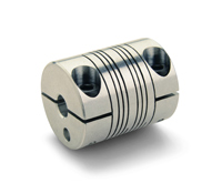
The first design - MWC/MWS, PCR/PSR - utilizes two sets of two beams and are available in inch, metric and inch-metric shaft sizes as standard items. The couplings have a compact design that allows for easy interchange with many single beam couplings and fits easily into small areas. These are designed as lighter duty couplings with greater flexibility that are best utilized in low torque application such as encoders, tachometers, and other instrumentation. The length of the beams is kept relatively long - although much shorter than single beam couplings (~1.5 rotations vs. 3 or more) to maintain excellent flexibility in the coupling and has the additional benefit of dampening vibration in the system as well as shock loads. Flexibility allows for greater tolerance in installation and manufacture of the system without causing premature failure of the coupling and also protects expensive components from excessive bearing loads created by reactionary forces due to misalignment of shafts. At the same time, by keeping the beams shorter than single beam couplings and grouping multiple beams together, these couplings are able to achieve higher torque capabilities and torsional stiffness in a coupling that fits in the same overall envelope.
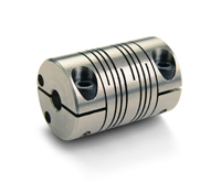
The second design involves two sets of three beams (FCR/FSR) which are also available from stock in inch, metric and inch-metric shaft sizes. The use of three beams in each set further allows for shortening the beams. This series utilizes beams that are only one full rotation in length, resulting in even higher torsional stiffness and torque capabilities as well as raises the natural frequency of the coupling giving the designer opportunity to tune the system to higher performance levels. The stronger beams are combined with larger body sizes to result in a coupling that is best suited for light duty power transmission applications such as connecting a servo motor to a ball screw. Bearing loads are higher than the two beam design so these are best utilized in applications with components such as servo motors and linear stages that tend to have more durable bearing support. This series also features Nypatch anti-vibration treatment on clamp screws to prevent screws from loosening in use.
Material Selection
Material is a factor that should be considered early in the specification of a beam coupling. Because the coupling is machined from a single solid piece, the specified material determines a vast majority of the performance characteristics of the coupling. Typically, beam couplings are machined from either aluminum or stainless steel but are also available in plastics such as Delrin, titanium, and other engineering grade materials.
Aluminum is the most common choice for material because it has the best mix of attributes for the most common beam coupling applications. Aluminum is lightweight and has an excellent strength to weight ratio which makes it ideal for motion control applications. The light weight allows the couplings to be designed with low inertia to allow for a high level of responsiveness in the system without having the coupling diminish this performance characteristic. Aluminum’s strength and fatigue resistance allows for long, service free life, even in demanding applications. Aluminum can be treated with an electrolytic passivation process called anodizing to enhance the finish, durability, and corrosion resistance.
Stainless steel is the next most common choice for beam couplings. Most frequently, stainless steel is chosen to give increased strength to coupling. Stainless steel couplings are typically about twice as strong as an aluminum coupling of the same design and have much higher torsional stiffness as well. However, stainless steel has its tradeoff as well – inertia. Stainless steel has a mass almost 3 times that of aluminum which creates a coupling with relatively high inertia which can diminish the responsiveness of the system. For this reason, designers should be cautious of installing stainless steel couplings in motion control systems. The best applications for stainless steel are ones that encounter environmental issues such as weather, temperature extremes, chemicals or exposure to vacuum.
Other materials, such as titanium and Delrin, are far less commonly used. Typically, these are specialty applications and require special designs. For titanium, the costs and difficulty of machining keep this from being a viable option except absolutely necessary to the application - typically aerospace. Delrin has some advantages in that it has less mass and inertia than even aluminum and has the additional benefit of electrical isolation which can be important for applications with components that can be damaged or suffer interference from stray currents passing thru the coupling. However, Delrin has very low strength and can only be suitably used in applications with extremely low torque requirements. A better option for applications requiring isolation is to use aluminum couplings with insulating inserts. This has the added benefit of isolation without sacrificing coupling strength making the combination well suited for many applications.
Summary
Couplings are an integral piece of a motion control systems performance. Beam couplings are a versatile coupling that can provide excellent characteristics if applied correctly. Many factors must be considered in the selection of the right coupling for an application. Understanding these factors can lead to reduced coupling failure and better system performance.