The store will not work correctly when cookies are disabled.
Due to Microsoft's discontinuation of updates, including security, certain functionality such as checkout and CAD may not work for you. We recommend using Google Chrome, Microsoft Edge, Firefox, or Safari to ensure full functionality.Thank you - the Ruland team
Large jaw couplings are now being offered for bore sizes up to 1-3/4” or 45 mm and torque capacities of 2,655 in-lbs (300 Nm). These new large jaw couplings are designed for use in precision systems with high deceleration and acceleration curves, such as those found in semiconductor, solar, conveyor, and warehouse automation applications.
Pre-assembled modular mounting systems are designed for adjustability across many mounting applications. Conveyor mounting systems emphasize strict parallel installation using a flange-bolt base and a conveyor rail guide. Sensor mounting systems offer flexibility in a mounting application with adjustable or 90-degree connectors, two-way bases, and various mounting brackets. Both systems include stainless steel rods (with or without scale) from 100mm to 300mm in length, zinc clamping levers, and connectors that allow adjustment of the rods’ position.
Mountable shaft collars with face holes are designed to mate directly with components such as sprockets, pulleys, and metallic plates. Ruland manufactures them with drilled holes for mounting flexibility or threaded holes for the most secure connection between the collar and mated component. They are offered in steel, aluminum, and 303 stainless steel in bore sizes ranging from 3/8” to 2” and 10mm to 50mm.
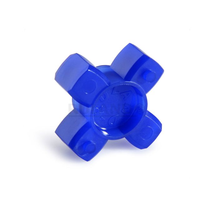
Ruland MJS15-5-A JD10/15-92Y MJS15-3-A, 5mm x 3mm Jaw Coupling Bundle, Aluminum, Set Screw Style Hubs, 15.0mm OD, 21.8mm Length
PRODUCT SPECIFICATIONS
Ruland JD10/15-85B is a zero-backlash jaw coupling spider designed to fit Ruland hubs that have an 0.590" (15.0mm) OD. It is a component in a three-piece design consisting of two aluminum hubs and an elastomeric insert called the spider creating a lightweight low inertia coupling capable of speeds up to 8,000 RPM. This three-piece design allows for a highly customizable coupling that easily combines clamp or set screw hubs with inch, metric, keyed, and keyless bores. JD10/15-85B is made from polyurethane and has 85 Shore A hardness allowing for the highest level of dampening with the lowest torque capacity. Ruland jaw couplings have a balanced design for reduced vibration at high speeds. Hardware is metric and tests beyond DIN 912 12.9 standards for maximum torque capabilities. JD10/15-85B is RoHS3 and REACH compliant.
PRODUCT SPECIFICATIONS
Dimensions
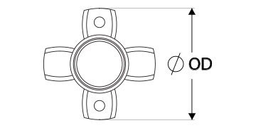
Outer Diameter (OD)
0.590 in (15.0 mm)
Performance Specifications
Rated Torque
Recommended torque based on slippage on the shaft.
2.4 in-lb (0.27 Nm)
Angular Misalignment
Max angle of the shaft axes relative to each other.
1.0°
Peak Torque
The torque where the insert will permanently deform and lose elasticity. This will result in loss of zero-backlash.
4.8 in-lb (0.5 Nm)
Parallel Misalignment
Shafts are parallel to each other, but not in-line with each other. They are offset.
0.005 in (0.13 mm)
Torsional Stiffness
Measures the rigidity of the coupling. The more rigid the coupling, the less windup it will have.
2.2 lb-in/Deg (0.25 Nm/Deg)
Moment of Inertia
0.00005 lb-in2 (1.492 X 10⁻⁸ kg-m2)
Axial Motion
The amount shafts can move closer to or away from each other. This is meant for thermal expansion of the shafts. No axial force can be placed on the coupling.
0.020 in (0.51 mm)
Maximum Speed
8,000 RPM
Full Bearing Support Required?
Full bearing support is a bearing in close proximity to both sides of the coupling to prevent axial loads that could result in rapid coupling failure.
Yes
Zero-Backlash?
Zero-backlash ensures there is no loss of motion during operation.
Yes
Additional Information
Weight (lbs)
0.001400
Temperature
Minimum and maximum operating temperature. Operating temperature includes ambient temperature plus or minus factors such as system heat generated during operation, washdown, vacuum, etc...
UNSPC
Code used to identify products to standardize nomenclature around the world.
31163011
Recommended Gap Between Hubs
The recommended installation gap between the two hubs.
0.020 in (0.50 mm)
Product Notes
Note 1
Performance ratings are for guidance only. The user must determine suitability for a particular application.
Note 2
Torque ratings for the couplings are based on the physical limitations/failure point of the spiders. Under normal/typical conditions the hubs are capable of holding up to the nominal torque of the spiders. In some cases especially when the smallest standard bores are used or where shafts are undersized slippage on the shaft is possible below the nominal torque of the spiders. Keyways are available to provide additional torque capacity in the shaft/hub connection when required. Please consult technical support for more assistance.
Prop 65
Required for the US State of California only.
Align the bores of the jaw coupling hubs on the shafts that are to be joined and determine if the misalignment parameters are within the limits of the coupling.(Angular Misialignment: 1.0 deg, Parallel Misalignment: 0.005 in (0.13 mm), Axial Motion: 0.02 in (0.51 mm))
Fully tighten the screw(s) on the first hub to the recommended seating torque using a hex torque wrench.
Insert a spider into the jaws of the first hub until the raised points contact the base of the hub.
Insert the jaws of the second hub into the spider openings until the raised points contact the base of the second hub. Some force will be required to insert the second hub. This is normal.
Assure that a gap is maintained between the two hubs so there is no metal to metal contact. Fully tighten the screw(s) on the second hub to the recommended seating torque.