
CPTDK35-16-A CPFRG35/56-AT CPTDK35-8-A
PRODUCT SPECIFICATIONS
PRODUCT SPECIFICATIONS
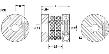
| Dimensions | |||
|---|---|---|---|
|
Bore (B1) |
1.0000 in |
B1 Max Shaft Penetration |
0.984 in |
|
Keyway (K) |
1/4 in |
Outer Diameter (OD) |
2.205 in (56.0 mm) |
|
Bore Tolerance |
+0.003 in / +0.001 in |
Hub Width (LH) |
0.472 in |
|
Length (L) |
2.008 in (51.0 mm) |
Space Between Hubs (LS) |
1.062 in (27.0 mm) |
| Fastening Hardware | |||
|
Forged Clamp Screw |
M5 |
Screw Material |
Alloy Steel |
|
Hex Wrench Size |
4.0 mm |
Screw Finish |
Black Oxide |
|
Seating Torque |
5.7 Nm |
Screw Location (R) |
21 mm |
|
Number of Screws |
1 ea |
||
| Performance Specifications | |||
|
Rated Torque |
14 Nm |
Angular Misalignment |
1.0° |
|
Peak Torque |
16 Nm |
Torsional Stiffness |
14.40 Nm/Deg |
|
Axial Motion |
0.039 in |
Parallel Misalignment |
0.059 in |
|
Maximum Speed |
10,000 RPM |
Recommended Inserts |
|
|
Full Bearing Support Required? |
Yes |
Zero-Backlash? |
Yes |
|
Balanced Design |
Yes |
||
| Additional Information | |||
|
Weight (lbs) |
0.156600 |
Temperature |
-22°F to 175°F (-30°C to 80°C) |
|
Material Specification |
6082 Aluminum Bar |
Finish |
Clear Anodized |
|
Finish Specification |
Clear Anodized |
Manufacturer |
Schmidt Kupplung |
|
UPC |
634529224526 |
Country of Origin |
Germany |
|
Tariff Code |
8483.60.8000 |
UNSPC |
31163022 |
| Product Notes | |||
|
Note 1 |
Stainless steel hubs are available upon request. |
Note 2 |
Performance ratings are for guidance only. The user must determine suitability for a particular application. |
|
Note 3 |
Torque ratings for the couplings are based on the physical limitations/failure point of the inserts. Under normal/typical conditions the hubs are capable of holding up to the rated torque of the inserts. In some cases, especially when the smallest standard bores are used or where shafts are undersized, slippage on the shaft is possible below the rated torque. Keyways are available to provide additional torque capacity in the shaft/hub connection when required. Please consult technical support for more assistance. |
Prop 65 |
|
| Installation Instructions | |||
|
Installation Video |
Installation Instructions |
|
|
 WARNING This product can expose you to chemicals including Ethylene Thiourea and Nickel (metallic), known to the State of California to cause cancer, and Ethylene Thiourea known to the State of California to cause birth defects or other reproductive harm. For more information go to
 | Dimensions | |||
|---|---|---|---|
|
Insert Thru Hole F |
0.709 in (18 mm) |
Outer Diameter (OD) |
2.205 in (56.0 mm) |
| Performance Specifications | |||
|
Torque Specifications |
Torque ratings vary with hub selection |
Misalignment |
Misalignment ratings vary with hub selection |
| Additional Information | |||
|
Weight (lbs) |
0.023700 |
Temperature |
-22°F to 175°F (-30°C to 80°C) |
|
Material Specification |
Acetal |
Manufacturer |
Schmidt Kupplung |
|
UPC |
634529223055 |
Country of Origin |
Germany |
|
Tariff Code |
8483.60.8000 |
UNSPC |
31163022 |
| Product Notes | |||
|
Note 1 |
Performance ratings are for guidance only. The user must determine suitability for a particular application. |
Prop 65 |
|
| Installation Instructions | |||
|
Installation Instructions |
|
Installation Video |
|
| Dimensions | |||
|---|---|---|---|
|
Bore (B1) |
0.5000 in |
B1 Max Shaft Penetration |
0.984 in |
|
Keyway (K) |
1/8 in |
Outer Diameter (OD) |
2.205 in (56.0 mm) |
|
Bore Tolerance |
+0.002 in / +0.001 in |
Hub Width (LH) |
0.472 in |
|
Length (L) |
2.008 in (51.0 mm) |
Space Between Hubs (LS) |
1.062 in (27.0 mm) |
| Fastening Hardware | |||
|
Forged Clamp Screw |
M5 |
Screw Material |
Alloy Steel |
|
Hex Wrench Size |
4.0 mm |
Screw Finish |
Black Oxide |
|
Seating Torque |
5.7 Nm |
Screw Location (R) |
21 mm |
|
Number of Screws |
1 ea |
||
| Performance Specifications | |||
|
Rated Torque |
14 Nm |
Angular Misalignment |
1.0° |
|
Peak Torque |
16 Nm |
Torsional Stiffness |
14.40 Nm/Deg |
|
Axial Motion |
0.039 in |
Parallel Misalignment |
0.059 in |
|
Maximum Speed |
10,000 RPM |
Recommended Inserts |
|
|
Full Bearing Support Required? |
Yes |
Zero-Backlash? |
Yes |
|
Balanced Design |
Yes |
||
| Additional Information | |||
|
Weight (lbs) |
0.182900 |
Temperature |
-22°F to 175°F (-30°C to 80°C) |
|
Material Specification |
6082 Aluminum Bar |
Finish |
Clear Anodized |
|
Finish Specification |
Clear Anodized |
Manufacturer |
Schmidt Kupplung |
|
UPC |
634529224564 |
Country of Origin |
Germany |
|
Tariff Code |
8483.60.8000 |
UNSPC |
31163022 |
| Product Notes | |||
|
Note 1 |
Stainless steel hubs are available upon request. |
Note 2 |
Performance ratings are for guidance only. The user must determine suitability for a particular application. |
|
Note 3 |
Torque ratings for the couplings are based on the physical limitations/failure point of the inserts. Under normal/typical conditions the hubs are capable of holding up to the rated torque of the inserts. In some cases, especially when the smallest standard bores are used or where shafts are undersized, slippage on the shaft is possible below the rated torque. Keyways are available to provide additional torque capacity in the shaft/hub connection when required. Please consult technical support for more assistance. |
Prop 65 |
|
| Installation Instructions | |||
|
Installation Video |
Installation Instructions |
|
|