

MCPRD75-40-A CPFRG48/75-AT MCPRD75-34-A
PRODUCT SPECIFICATIONS
PRODUCT SPECIFICATIONS
| Dimensions | |||
|---|---|---|---|
|
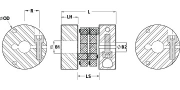
Agujero (B1) |
40 mm |
Agujero (B2) |
34 mm |
|
Diámetro exterior OD |
75,0 mm (2,953 pulg) |
Longitud L |
73,0 mm (2,874 pulg) |
|
Espacio entre los cubos (LS) |
1,456 pulg (37,0 mm) |
||
| Dimensions | |||
|---|---|---|---|
|
Agujero (B1) |
40 mm |
Penetración del eje máximo (B1) |
18,0 mm |
|
Diámetro exterior OD |
75,0 mm (2,953 pulg) |
Tolerancia del agujero |
+0,09 mm / +0,03 mm |
|
Ancho del cubo (LH) |
18,00 mm |
Longitud L |
73,0 mm (2,874 pulg) |
|
Espacio entre los cubos (LS) |
1,456 pulg (37,0 mm) |
||
| Fastening Hardware | |||
|
Tornillo de abrazadera forjado |
M8 |
Material del tornillo |
Alloy Steel |
|
Tamaño de la llave hexagonal |
6,0 mm |
Acabado de los tornillos |
Black Oxide |
|
Par de apriete |
24,0 Nm |
Ubicación del tornillo R |
25 mm |
|
Número de tornillos |
1 cada |
||
| Performance Specifications | |||
|
Par recomendado |
30 Nm |
Desalineación angular |
1,0° |
|
Pico del par de transmisión |
40 Nm |
Rigidez torsional |
21,00 Nm/Deg |
|
Movimiento axial |
1,50 mm |
Desalineación paralela |
2,00 mm |
|
Velocidad máxima |
7,500 RPM |
Recommended Inserts |
|
|
Bearing Support Required |
sí |
¿Juego cero? |
Sí |
|
¿Diseño equilibrado? |
Sí |
||
| Additional Information | |||
|
peso |
0.173200 |
Temperatura |
-30°C a 80°C |
|
Especificación de material |
Barra de aluminio AISI 6082 |
Acabado |
Anodizado claro |
|
Especificación de acabado |
Clear Anodized |
Fabricante |
Schmidt Kupplung |
|
UPC |
634529225530 |
País de origen |
Alemania |
|
Tariff Code |
8483.60.8000 |
UNSPC |
31163022 |
| Product Notes | |||
|
Nota 1 |
Stainless steel hubs are available upon request. |
Nota 2 |
Performance ratings are for guidance only. The user must determine suitability for a particular application. |
|
Nota 3 |
Torque ratings for the couplings are based on the physical limitations/failure point of the inserts. Under normal/typical conditions the hubs are capable of holding up to the rated torque of the inserts. In some cases, especially when the smallest standard bores are used or where shafts are undersized, slippage on the shaft is possible below the rated torque. Keyways are available to provide additional torque capacity in the shaft/hub connection when required. Please consult technical support for more assistance. |
Prop. 65 |
|
| Installation Instructions | |||
|
Video de instalación |
Instrucciones de instalación |
|
|
 WARNING This product can expose you to chemicals including Ethylene Thiourea and Nickel (metallic), known to the State of California to cause cancer, and Ethylene Thiourea known to the State of California to cause birth defects or other reproductive harm. For more information go to
 | Dimensions | |||
|---|---|---|---|
|
Inserto de controlflex F |
1,122 pulg(28.5 mm) |
Diámetro exterior OD |
75,0 mm (2,953 pulg) |
| Performance Specifications | |||
|
Torque Specifications Hub |
Torque ratings vary with hub selection |
Misalignment Hub |
Misalignment ratings vary with hub selection |
| Additional Information | |||
|
peso |
0.030400 |
Temperatura |
-30°C a 80°C |
|
Especificación de material |
Acetal |
Fabricante |
Schmidt Kupplung |
|
UPC |
634529223062 |
País de origen |
Alemania |
|
Tariff Code |
8483.60.8000 |
UNSPC |
31163022 |
| Product Notes | |||
|
Nota 1 |
Performance ratings are for guidance only. The user must determine suitability for a particular application. |
Prop. 65 |
|
| Installation Instructions | |||
|
Instrucciones de instalación |
|
Video de instalación |
|
| Dimensions | |||
|---|---|---|---|
|
Agujero (B1) |
34 mm |
Penetración del eje máximo (B1) |
18,0 mm |
|
Diámetro exterior OD |
75,0 mm (2,953 pulg) |
Tolerancia del agujero |
+0,09 mm / +0,03 mm |
|
Ancho del cubo (LH) |
18,00 mm |
Longitud L |
73,0 mm (2,874 pulg) |
|
Espacio entre los cubos (LS) |
1,456 pulg (37,0 mm) |
||
| Fastening Hardware | |||
|
Tornillo de abrazadera forjado |
M8 |
Material del tornillo |
Alloy Steel |
|
Tamaño de la llave hexagonal |
6,0 mm |
Acabado de los tornillos |
Black Oxide |
|
Par de apriete |
24,0 Nm |
Ubicación del tornillo R |
25 mm |
|
Número de tornillos |
1 cada |
||
| Performance Specifications | |||
|
Par recomendado |
30 Nm |
Desalineación angular |
1,0° |
|
Pico del par de transmisión |
40 Nm |
Rigidez torsional |
21,00 Nm/Deg |
|
Movimiento axial |
1,50 mm |
Desalineación paralela |
2,00 mm |
|
Velocidad máxima |
7,500 RPM |
Recommended Inserts |
|
|
Bearing Support Required |
sí |
¿Juego cero? |
Sí |
|
¿Diseño equilibrado? |
Sí |
||
| Additional Information | |||
|
peso |
0.190300 |
Temperatura |
-30°C a 80°C |
|
Especificación de material |
Barra de aluminio AISI 6082 |
Acabado |
Anodizado claro |
|
Especificación de acabado |
Clear Anodized |
Fabricante |
Schmidt Kupplung |
|
UPC |
634529225509 |
País de origen |
Alemania |
|
Tariff Code |
8483.60.8000 |
UNSPC |
31163022 |
| Product Notes | |||
|
Nota 1 |
Stainless steel hubs are available upon request. |
Nota 2 |
Performance ratings are for guidance only. The user must determine suitability for a particular application. |
|
Nota 3 |
Torque ratings for the couplings are based on the physical limitations/failure point of the inserts. Under normal/typical conditions the hubs are capable of holding up to the rated torque of the inserts. In some cases, especially when the smallest standard bores are used or where shafts are undersized, slippage on the shaft is possible below the rated torque. Keyways are available to provide additional torque capacity in the shaft/hub connection when required. Please consult technical support for more assistance. |
Prop. 65 |
|
| Installation Instructions | |||
|
Video de instalación |
Instrucciones de instalación |
|
|


